Tuesday, November 11, 2008

Stretch SplineIK for Head Rig Part 2

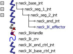
Create joint chain for neck section; create joint chain with 3 equal joint sections. We can use snap and grids to assist create joint chain, and then rename it properly.


Joint chain for neck section


Rename the joints properly after created


1. Create a splineIK for the joints. The splineIK takes the joints and snaps them to nurbs curve. Manipulate the curve, and it will pull the joints around

  • Choose Skeleton > Spline Ik Hanle Tool > Option Box
  • Reset the tools


reset the Spline Ik Hanle Tool

  • Click on the first joint of the joint chain – neck_base_jnt
  • Click on the last joint of the joint chain – neck_end_jnt

An ikHandle, end effector and Curve will be created, rename them with proper names as the following picture. To check the splineIK, select neck_Ik_crv, and manipulate the CVs on the curve.
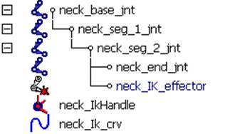

SplineIk had been created and renamed
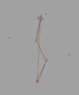


Moving the joint chain by manipulate the curve


2. The CVs of the curve cannot be animation directly; we have to assign controls to manipulate the curve. We can create cluster on each CVs in order to animate the CVs, yet it is quite tedious. The alternative is to create 2 individual joints on the both ends of the joint chain, smooth skinning the curve to the joints which is quick set up.

  • Create two individual joints, and snap them on the neck_base_jnt and neck_end_jnt, holding down v Key for point snap to help in the snapping joint.
  • Rename the two joints to neck_IK_base_ctrl_jnt and neck_IK_end_ctrl_jnt
  • Select neck_Ik_crv, neck_IK_base_ctrl_jnt and neck_IK_end_ctrl_jnt
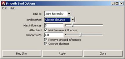
  • Choose Skin > Bind Skin > Smooth Bind > Option Box
  • Reset the settings
  • Select Bind methods > closest distance
  • Bind Skin


Renaming nodes


The smooth bind options

  • Create two nurbs curves, model those two curves in the shapes what make scene to animators
  • Rename the two curves into neck_Ik_end_ctrl_crv and neck_Ik_base_ctrl_crv respectively
  • Snap neck_Ik_base_ctrl_crv on neck_IK_base_ctrl_jnt and neck_Ik_end_ctrl_crv on neck_IK_end_ctrl_jnt
  • Set Freeze transformation to neck_Ik_end_ctrl_crv and neck_Ik_base_ctrl_crv
  • Parent the neck_Ik_base_ctrl_crv to neck_IK_base_ctrl_jnt and neck_Ik_end_ctrl_crv to neck_IK_end_ctrl_jnt
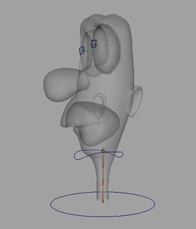
Create animation control curve for manipulate the splineIK
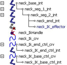


Parent the neck_Ik_base_ctrl_crv to neck_IK_base_ctrl_jnt and neck_Ik_end_ctrl_crv to neck_IK_end_ctrl_jnt


The splineIK had been set up

The splineIK had been set up; both ends of the splineIK can be animated with the animation control curve. Next step will create the stretchy feature on the splineIK joint chain.

Monday, November 10, 2008

Stretch SplineIK for head rig Part 1


The joints chains for head


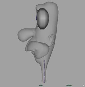
As the cartoony style of the animation, the head of the character may not be maintained in the anatomical structure. The range of the movement is not only based on the lower jaw and the neck. According to the animatic, the upper jaw of character is not stick rigidly on the head joint and lifts up from the lower jaw, the eyes and forehead has to been stretch independently. The rig of the head has to basically broken in order to achieve the requirements.

The head motion of character in the animatic

So, I broke the head rig into four sections, each can be moved and stretched independently to the others and has to been linked one by one:
1. Forehead, eyes and nose.
2. Upper jaw
3. Lower jaw
4. And neck


The head had been into 4 parts for the rigging

The rig is used in each part which has to allow for bend, stretch, twist and independent motion of both ends. There are a few different techniques to achieve those effects. The most typical way is the stretchy splineIK system which had been presented by Jason Schleifer of Dreamworks & WETA in the DVD “Intergrading A Creature Animation Rig Within A Production Pipeline”. The content of the DVD is actually AWGUA Maya Master Class August 2001, although the technique has been existing for almost 8 years already, it is still popular and using for spine setup as it is easy to setup. The ribbon spine is another new way of building an IK-like spine rig which presented by Aaron Holly, lead character technical director of Digital Domain, in his DVD “Rigging For Feature Animation”. This technique gives animators greater control and more flexibility over their spine animation, yet this technique has to be involved with Maya Hair follicles, follicles is only featured Maya Unlimited version and may be accessed by some users. The stretchy splineIK system is normally used for the spine rig, yet I intended to use the technique for the head rig in my project.

Friday, November 7, 2008

Thursday, November 6, 2008

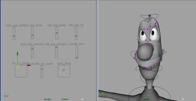
The Blend Shape Control

Although the book, “Stop Staring: Facial Modeling and Animation Done Right!” , written by Jason Osipa was released for 5 years already, the setups method for blend shapes presents in that book is still thoroughly today. The great thing about Jason Osipa’s setup is multiple blend shapes can be controlled by the translation of X and Y of a 2D slider, which reduce the controls animators have to deal with. Furthermore, certain shape would not happen at the same time, such as smiles and frowns. When animators increase the effect of target shape A, they have to reduce the influence of target shape B. By putting two of those shapes on opposite ends of the same control, the amount of work can be reduced.


Multiple Blend shapes can be controlled by a 2D slider controller

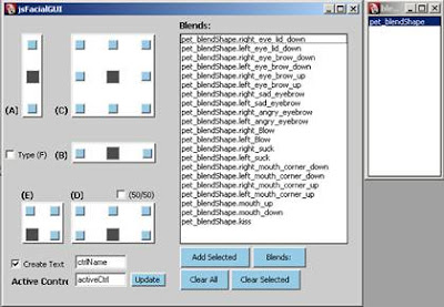
According to the explanation of Jason Osipa in his book, the weigh of blendShape can be link with the translation of X and Y of a 2D slider by expression. As “Osipa” style blend shape controls become famous and popular, Judd Simantov, technical director of Naughty Dog, had written Mel script jsFacialWin for “Osipa” style which can be downloaded from Jason Osipa’s website. It makes Jason’s setup easy to create by giving us a GUI to create all the different sliders and we can link blendshapes into the sliders.


GUI to create all the different sliders and link blendshapes into the sliders.

Steps for using jsFacialWin to create slider controls and link blend shape into the sliders

1. Load the blendShapes into the GUI first; hit the “Blends:” button, select the Blendshape node you want to load into the GUI.
2. Hit “Add selected” button, all the target shapes of the selected blendshape node show up in the blends text scroll list (name your objects properly is very important).
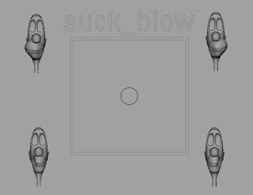
3. In the case of suck and blow slider, Type “suck_blow” in the text field below the sliders in the GUI.
4. Click on the grey box in the middle of the C type slider. A slider will been created in the scene.
5. Select the pet_blendShape.right_Blow from the blendshape scroll list, load it into the top right side of C slider, by hit the blue button in the top right of corner of the C slider GUI.
6. Select pet_blendShape.left_Blow and load it into the top left side of C slider.
7. Select pet_blendShape.left_Suck and load it into the bottom left side of C slider.
8. Select pet_blendShape.right_Suck and load it into the bottom right side of C slider.
9. Test out the slider view.


Target shapes are link into the corners of 2D Slider by using jsFacialWin GUI


References for creating target shapes and blend shape control

Osipa, J. (2003). Stop Staring: Facial Modeling and Animation Done Right. San Francisco: Sybex Inc.
Osipa, J. (2008). Osipa Entertainment. Retrieved March 20, 2008 from http://www.jasonosipa.com/

Sunday, November 2, 2008

Creating Blend Shape for Head


Target shapes for blend shape

According to the story of the animation, no speaking is required for character, and the anatomic structure has not to be carefully considered as the cartoony style. Beside the blend shape, joints and “On face control” are used together in the head rig, so the amount of the target shapes are relatively small then the ordinary characters. The main factors in creating target shape models are the emotion of character and the eye blinking movement. Some tips and tricks for creating target shape models.

Most of the target shapes are the duplicate of the original head then are modified, take notice of the translation of the target shapes, don’t freeze transformation of target shapes, otherwise the head will translate towards to the target shapes during the morphing.

Using deformer to assist at modification the target shapes, such as soft modification tool and cluster with paint weight, which can change the mesh partially and smoothly. Delete history after the modification, but do not freeze transformation.


Using soft modification tool to make target shapes


Using cluster with paint weight for the target shapes

Blend shape deformer is linearly interpolated form one shape into another, which may not fulfill what you need. Thus, add In-Between Target for existing target object shapes. In the case of the eyelid, I used two more shapes for the in-between target. In the add blend shape target options, the target index is quite confusing to users.

You can actually identify the appropriate value for Target Index is by looking at the order of the target sliders in the Blend Shape Editor (Window > Animation Editors > Blend Shape). Target Index value for the left-most target slider would be 1, the next 2, and so on.


The target index of blend shape deformer

The target shapes should be separated for deformation left and right side of head individually; in order to create asymmetrical facial expression. Yet the target shape cannot be mirrored or flipped by negative scaling since the vertex order will be not changed, you may have to remodel the same shape for the other side. Fortunately, there are tons of free Mel scripts to mirroring or flipping the target shape which can be found in the internet, using those free Mel script to save your time.

Saturday, November 1, 2008

The Stretchy Eye Balls

According to the finalized model, the eye balls of the character are not exact spheres; the eyes movement will be a problem as the pivot point is not located exactly at the center of the eye balls. Some studios would use texture project to make the pupils, but the pupils will be distorted and the projected image may not be stable after the geometry of the eye ball are stretched with the head. Jared Lindquist tried using rivet script and “Freeze Geometry’” of lattice to keep the pupils remains circular and attaching on the eye, and I had modified this method to make the eye stretch with the head properly.

1. Create a nurbs sphere for eye model; rename it to eye _geo and a polygon sphere roughly the same size; rename it to eye_rivet_base_geo. ( it’s good habit which rename all new nodes to some meaningful names after create, it will help to trace and solve problem)

The polygon sphere can be created by duplicate the nurbs sphere and convert into polygon.

Figure2 - a nurbs sphere for eye model and a polygon sphere

2. Use rivet script which was created by technical director Michael Bazhutkin, On the eye_rivet_base_geo, select two parallel edges in front of the location of pupil, and create a rivet. The locater will stick on the polygon face even thought the face has been translated or deformed. Rename locator to eye_rivet_loc.

Figure 3 - select two parallel edges in front of the eye_rivet_base_geo and create rivet

Figure 4 – a locator (rivet) is created accordingly and stick to that polygon

3. Position the eye _geo and eye_rivet_base_geo with rivet on same location, we can use point constrain to position two geometries on the exact same location:

  • Select the eye _geo then shift select eye_rivet_base_geo with rivet

  • Choose Constrain > Point to assign point constrain

Figure 5 –eye _geo and eye_rivet_base_geo snaped together

  • Delete the point constrain node under eye_rivet_base_geo.

Figure 6 – delete point constrain node under eye_rivet_base_geo in outliner

4. In the original idea of Jared Lindquist’s, the eyes are deformed and stretched by lattice, but it the lattice could not be deformed with and driven by the head rig. Instead of the lattice, I use wrap deformer as a main deformer for the eyes.

Create wrap deformer for eye_geo

  • Duplicate eye_geo and rename eye_wrap_base_geo

  • Scale eye_wrap_base_geo a bit, slightly larger than eye_geo and eye_rivet_base_geo, and wrap around them.

  • Select eye_geo first, and then shift select eye_wrap_base_geo,

  • Choose Create Deformers > Wrap, to create wrap deformer.

  • Select eye_geo, rename the wrap input node to eye_geo_wrap.

  • Set the Max Distance of eye_geo_wrap to 50.

Figure 7 –Set the Max Distance of eye_geo_wrap up to 50.

Create wrap deformer for eye_rivet_base_geo as well

  • Select eye_rivet_base_geo first, and then shift select eye_wrap_base_geo,

  • Choose Create Deformers > Wrap, to create wrap deformer.

  • Select eye_rivet_base_geo, rename the wrap input node to eye_rivet_base_geo _wrap.

  • Set the Max Distance of eye_rivet_base_geo _wrap to 50.

Figure 8 –Set the Max Distance of eye_rivet_base_geo _wrap up to 50.

5. eye_geo and eye_rivet_base_geo are deformed according to the shape of eye_wrap_base_geo and eye_wrap_base_geo can be bound on the head rig, so the eye can be stretch with head. But the CV for pupils could not remain in circular. Now we use the rivet and lattice to remain the shape of pupils.

Figure 9 - eye_geo and eye_rivet_base_geo are deformed according to the shape of eye_wrap_base_geo.

  • Reset the shape of eye_wrap_base_geo

  • Select the CV for pupils on eye_geo

Figure 10 - the CV for the pupils on eye_geo

  • Choose Create Deformers > Lattice, rename the ffdLattice to pupils_ffd_Lattice and ffdBase to pupils_ffd_Base. Select eye_geo and rename the ffd input node to pupils_ffd.

Figure 11 – create Lattice on the CV for pupils and rename properly

  • Set the division of S, T, U, for the pupils_ffd_shape to 2, and check the ‘Freeze Geometry’ option of pupils_ffd in the attributes editor

  • Parent pupils_ffd_Lattice under eye_rivet_loc

  • Figure 12 – the setting for pupils_Lattices

Now select both eye_geo and eye_rivet_base_geo, the CVs for pupils are remaining circular as the shape is frozen by the pupils_ffd. We can assign ramp texture and shader eye_geo. The shape of eye is driven by the eye_wrap_base_geo, deform the eye_wrap_base_geo to fit in the eye socket of the character and bind to head joint later on.

As the eye_geo and eye_rivet_base_geo have to rotate together, we can use orient constrains to make eye_rivet_base_geo following to eye_geo.

Figure 13 –pupils are remaining circular no meter how the eye had been stretched

Now the eye movement can been created by rotate the eye_geo, the pupils are remained circular no meter what shape of the eye ball. Group all the elements for eye into one group in order to clarify the scene and ready for next step.

Figure 14 – the move and deform the eye_wrap_base_geo to fit the eye into the eye socket.

The eye movement can been created by rotate the eye_geo.

References for marking stretchy eye ball

Lindquist, J. (2007). Nyeng! Stretchy eyes in Maya. Retrieved March 18, 2008 from http://www.nyeng.com/?page_id=345

Bazhutkin, M. (2007). Bazhutkin Software. Retrieved March 18, 2008 from http://www.geocities.com/bazhutkin/